


|
|
|
|
|
|
| Drott 80R at Work | Click images to expand |
This is a Drott 80R at work in 50-60 year old Douglas Fir Timber. The machine weighs in at around 50 tons, and is powered by a single Detroit Diesel 8V71 (318 hp) located in the lower unit. The "R" implies that this model has a raised cab for better visibility. With a different boom this machine is also usable as an excavator, in which case the raised cab would not be installed. It has a 2 position boom which allows the geometry to be adjusted for digging or working above ground.
The rubber tired chassis has not proven particularly popular in the logging industry because it is more expensive than track mounts and presents some challenges. While the lifting capacity is ample for almost any kind of timber, the rubber tired mount has its good points and bad points. It means that the machine can readily be driven from location to location which makes it ideal for thinning operations which require a lot of running around. However, since rubber mounts require stabilizers it is less convenient if you are only wanting to move a few feet to reach another log. Also the machine sits a lot higher than a track machine and is inherently less stable. Finally, if it is necessary to move it on the highway, it needs to be hauled, and height and weight make these machines very lowboy unfriendly. To transport these units requires 11 axles (on the truck and lowboy) and a crane to remove the cab to reduce the overall height (It is still over 14 feet high however). The book says these machines weigh in at around 85,000 lbs. The working weight is about 100,000 lbs however.

|

|
Track machines can be and usually are engineered much closer to the ground as they don't need swing clearance over the tires. The lower design improves stability and simplifies hauling, but also presents a safety issue in that the swinging house is low enough to be a hazard to workers. In recent years there has been a trend toward 'loader logging' in which a track laying loader is driven out into the woods and is used to simply 'relay' the logs from the stump to the landing, by repeatedly picking them up and swinging them in the landing direction. The methodology obviously cannot be employed with a Rubber tired loader which needs a good level hard surface road on which to operate. In recent years, a few manufactures have made a special carbody (what they call the tracks and lower unit of an excavator/loader) with extra high ground clearance (around 3 feet) and a high turntable (5-6 feet) which is particularly suitable for loader logging in regrowth clearcuts. The Rubber Tired Mount has been very successful however in thinning operations such as the one you see in this photograph where the loader must work in tight quarters in a small landing.

|
One of th fascinating issues that comes up with Rubber mounted loaders has to do with locomotion. We have seen these machines designed with a single engine in the upper unit, a single engine in the lower unit, and with 2 engines. The problem is that they need tremendous power on the driving wheels, and also tremendous amounts of oil to run the hydraulics on the boom. The problem is that all of whatever must move from one unit to the other through the 'circle'. Things get very crowded in the center of the circle, and there is no right answer. For example, we have an older Dico 166 on a maximount ( 4 rubber truck tires). It has a single engine in the upper unit. It requires a mechanical drive shaft, air controls for the brakes, hydraulic circuits for the stabilizers, and a hydraulic circuit for the steering to go down the center. The bizarre gear train is famous for its failures. Small wonder, but the configuration allows for a short lower unit permitting 'all the way around work' similar to that allowed by a track machine.
In Contrast the Drott has a single engine in the lower unit. This means the engine is in the way. The machine has a front and a back and the engine sticks out on the front. The boom will swing over the engine house, but practically speaking you are limited in your ability to 'work all the way around' the machine. The tail swing must clear the engine enclosure also which implies that the unit must be designed with a very short tail swing, which in turn implies that an extraordinary counterweight is required increasing the overall weight of the machine. The drive train, however, is conventional and durable. The engine is followed by an automatic transmission and a transfer case which supports 4-wheel drive. The components are scarcely different from those found under any 4X4 vehicle, only larger. But then the problems begin. The hydraulic pumps (2 ea. -70 G.P.M.) are mounted on the converter and that oil must (except when running the stabilizers) 'go upstairs'. Likewise air (for the brake controls) must pass upstairs along with controls for the transmission shifter, (mechanical) the throttle (brake fluid circuit), and the steering (hydraulic)., The balance of the needed controls are electric turning on rotating electrical contacts. This includes electric remotes on the stabilizers, start and stop functions for the engine and even machine lighting as well as engine instrumentation. Heat is the enemy of hydraulic systems, and restricted convoluted flow patterns for oil generate heat. Enough said. The rotating monster creates its share of grief but is probably over all a better solution than the Engine Up design. Drott is the only manufacturer who has used this design, and it clearly shares component design with some of their hydrocranes which use an engine down design on large rubber tires.

|
With the engine down, There is distinctly an engine compartment that sticks above the deck level. This limits the tail swing area and the space available for a counterweight. The Drott uses a block of concrete the width of the machine and about 3 feet high and 18 inches deep in the back for a counterweight. The upper unit has 360 degree rotation and the boom can work over the engine 'sort of'. With the boom cylinder toggle in the 'high position' the boom won't hit the engine house, but will swing over it at all times. As a log loader, this is generally adequate unless you are trying to reach down over a bank in which case you have to reset the toggle to the low position. Generally speaking, however one avoids working over the front of the machine whenever possible. This contrasts to a track machine that really has no front or back except for the purposes of travel.

|
| Link-Belt 3400 on Carrier Mount |
As noted, the 3rd alternative is a 2 engine design. A 2 engine machine is often designed much like a 'truck mount' crane. It will appear on a 3 axle carrier and the lower unit will look much like a truck, although often it won't have a cab since the controls will allow it to be 'driven' from the upper cab. These machines often have superior fuel economy, since the engine driving the oil pumps can be optimized for that function, without the necessity of providing the extra power necessary to drive the machine. The problems include cost and usability. They are about as graceful on soft roads as an overweight dump truck and they provide no pretence of an ability to work 'all the way around' The second engine presents an additional maintenance issue which is more than trivial. Under used engines spoil rapidly and it is very common for the locomotion engine (lower unit) to fail for some reason before the upper engine which sees a lot more use. These 2 engine units tend to be the most 'driveable' but the least maneuverable, and are generally a pain to use because of their difficulty in 'working all the way around'. Their driveabilitly is their strong point. They can be driven down the highway at almost highway speeds (25-35 mph), while the DROTT is effectively limited to 5-10 MPH. It will drive faster, but with the short wheelbase, it begins bouncing uncontrollably at higher speeds.
These problems with the rubber tired log loader design likely account for their limited popularity. There is simply no 'right way to build one. If the engine is up, there is no pretty way to get enough power to the drive train to attain the speed and gradeability expected of a rubber tired unit, and if the engine is down the engine is in the way, and all the oil has to go through a rotating valve which is a problem. It is simply a no win situation. All of this doesn't mean that a track machine is all wonderful. Contemporary machines use hydraulic drives for locomotion and always have the engine in the upper unit. Oil must go through the circle for travel but since this is a minority of the time it works fairly well. Track machines are are usually very slow at travel (1 to 3 MPH) so the power expected for a Rubber mount which is suppose to be able to achieve speeds of 25 MPH or so is not required. Speed is clearly an issue. The operators want/need to move the machines rapidly, but the track undercarriages disintegrate in geometric proportions to the travel speed. Track undercarriages are enormously expensive and difficult to repair (as compared to fixing a flat tire). The low travel speeds and rapid wear patterns characteristic of a track undercarriage imply that track machines should be hauled and not driven from job site to job site. This takes a lot of time and bother which is a major drawback, particularly if a low volume thinning operation is the order of the day. Who wants to load and haul a log loader on multiple occasions per day? How do you get anything else done, and you surely have a lowboy on duty almost as an adjunct of the process. The rest of the story is that if you are going to haul a track loader you need a haul road that is of even better quality than required to drive a rubber mount loader. Lowboys with 50 ton loaders simply do not navigate steep, crooked muddy roads very well, particularly if used in conjunction with a highway truck-tractor. An off highway truck (larger, heavier, stronger) will improve the situation but still is not a loggers dream. A rubber tired log loader can almost always be driven anywhere you would expect a log truck to go, but the same simply can't be said of a heavily laden lowboy. The lowboy will weigh more and track less well on the turns than the log truck which means that every soft shoulder is a disaster waiting to happen. You see, on the west coast, it is customary for log trucks to go into the woods hauling their trailers. This provides a light load (for traction) and makes them short and maneuverable. Log markets everywhere are down hill from the logs, so loaded the trucks generally have gravity on their side, but additionally, the classic west coast log trailer is 'stinger steered" which generally results in the trailer tires following exactly behind the truck no matter how short the corner. "Stinger steering' is a reference to the concept of fixing the trailer hitch on the truck a substantial distance behind the rear wheels of the truck (the stinger). As a consequence, when the truck is steer to say the left, the back of the truck swings to the right compensating for the tendency of the trailer to 'cut' the corner. The load, however doesn't ride on the hitch because if it did, the truck would up end. Rather, the logs are a 'bridge load' with the respective ends of the logs sitting on bunks or bolsters above the wheels.
This is in stark contrast to a lowboy which tracks on short corners like a classic long semi-trailer--not well. This is because the pivot point on the lowboy is the fifth wheel which of necessity must be mounted either over or slightly in front of the rear wheels. (otherwise the front wheels of the truck would come up). It will also be the first thing in (before the road is packed down if it is a new road) and the last thing out ( potentially after the log trucks have damaged or softened it from use) which is never the ideal time for use.
|
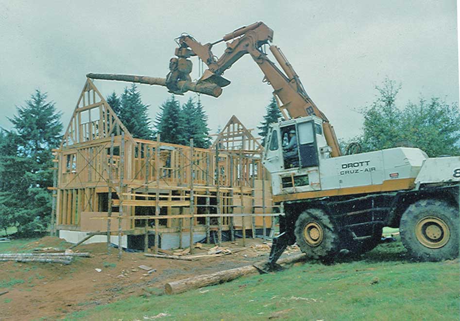
| Loggers Setting Trusses |
Loggers have a way of pressing these machines into duty for all sorts of things, and here you see this loader with a temporary 'gin pole' being used for a crane to set trusses on 3 story house. Loggers are often dismissed as simple 'brush apes', but in fact that have to be ever creative and imaginative to function. Every tree is different, and the weight and size of trees leaves little margin for error. Most of the machinery used in the logging industry is specially designed for its purpose, although in the case of this DROTT 80R it is only specially adapted.
The boom and the grapple and the extra hydraulic circuits associated with it (as well as the raised cab) set it apart from the more generic excavator model. This rubber tired chassis has appeared on some models of hydra-cranes, but at least in the Pacific Northwest, the excavator configuration is rare, but there just happens to be a Drott 80 Cruz Air Excavator on a nearby page, and the VanNatta Iron Museum generally for several other loaders and excavators. Note the difference in the boom.
A similar looking machine but much smaller (A Drott 40) is very common as a rubber mount excavator and is often used by cities and counties for road maintenance work. But alas, the Drott 40 has never made it in the woods because it simply isn't big enough. In the Northwest, logger invariably haul their log trailers back into the woods, and the log loader must be stout enough to unload the trailer. In as much as log trailers weigh 7-10,000 lbs, a loader that won't lift that much doesn't last long.
Date line May 2003:

|
| Broken Stub Axle |
Drott's have pretty much become history now. We have a few that still run, but the tracked excavator modified to be a log loader has taken over and these machines are long off the market. Over all the machines have served us well, but like every machine they do have their problems. Photographed here is a wheel that fell off of one. The stub axle broke as it was driving down a roadon the way to a new jobsite. As you can see from the photo, then the driving axle broke and there was a problem. We scrounged a new driving axle and stub axle from a parts machine and were back to work fairly soon. With an outrigger the machine was able to jack itself up. We made it lift its own tireback on with a sling tied to the boom so we were actually able to make the repairs without a crane or boom truck to handle the oversized parts.
Over all though the most frustrating part of a Drott is the center swivel which passes all the oil, and controls from the upper to lower unit. After the machine sit around for a while the electric contacts corrode and then nothing works right, though this can often be repaired by going 'round and round' until the contacts get rubbed clean again. Structurally, the later machines had some more iron in them in critical places. On the older models we have had the mainframe of the lower unit snap, and some of the machines we have looked at have had problems with the boom base. The booms themselves are so heavy that we have never seen a crack in one of them. They just don't break.
There is no loader around that we have had that will lift more than one of these things. With the outriggers down the width of the machine is about 18 feet, and the boom is relatively short. If it is only logs you are lifting they don't make a log it won't lift, but alas they are history. This is technology from the 1970's in the 21st century, and it doesn't cut it.
Dateline: Spring 2007 Well, we finally decided it was time to thin out our Drott collection with 4 of them getting cut up and heading to the scrap yard this spring. They are a create of th 1970's and 40 years is plenty long enough. You always learn something though when you scrap out a machine.
The incredible complexity of the machines is the thing that comes to mind was one goes to take it all apart. Since these machines are about to be history--I'm guessing we have some of the few survivors-- I'll try to describe the various subsystems that made these machines function.

|
| Drott down to tires |

|

|
| 1 electric/air switch for each direction | Electric relay on same mounting plate |
The controls are the most interesting from a complexity standpoint. When functioning properly, the usage was simple enough--- 4 rocker switches on the console in the cab, but what happened from there is amazing. Normally the pumps pushed all the oil up through the center swivel to the upper unit, but of course, the outriggers were on the lower unit. Bolted to the frame behind the rear axle were the spool valves for the outriggers. These are traditional manual spool valves. Two them each with 2 spools. They are operated by 2 way air cylinders, which are in activated by electric air valves which are powered by a an electric relay (activated by the 4 switches.)

|

|
| Main frame with Hole cut | It breaks from the square cutout upwards |