


|
|
| Gap Bed also L2 adapter for chuck |
|
|
| London Machine Tool Co. Ltd |
|
|
| Eighteen inch Union 4 jaw chuck |
|
|
| Overhead Drive |
|
|
| Two speed back Gears |
|
|
| Pilot Drill Hole |
|
|
| Two and one/eighth Drill |
|
|
| 2-3/4 bit with dog |
|
|
| Boring ever bigger |
|
|
| Lathe Set up for threading |
|
|
| Finished Hub |
|
|
| Rough plate in Lathe |
|
|
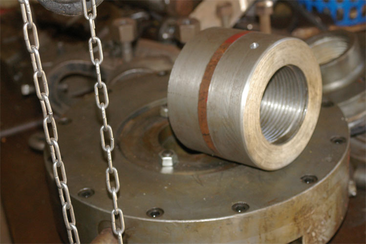
| Ring completed |
|
|
| Assembled |
|
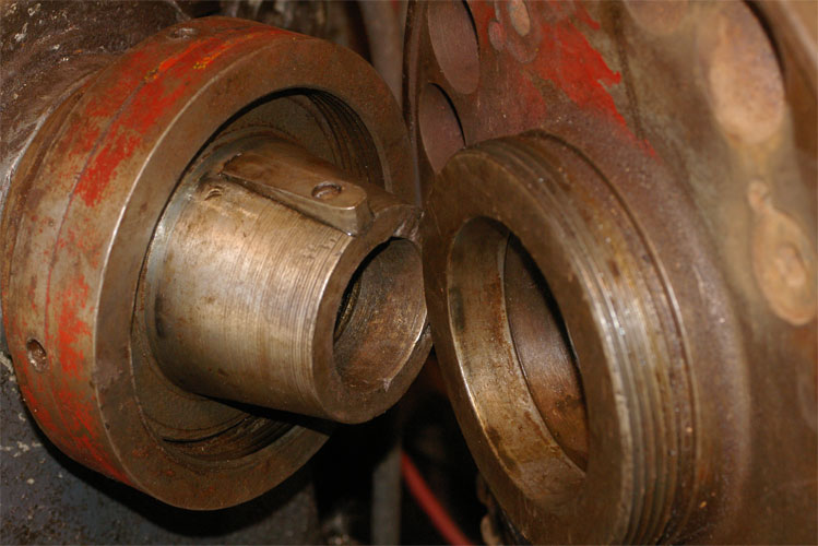
| 3 Jaw removal |

|
| Threaded Spindle |
|
| Unmounted assembly |
|
| Assembling Mount |
|
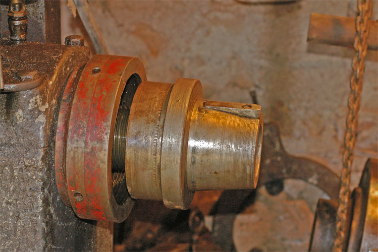
| L2 ready for Chuck |
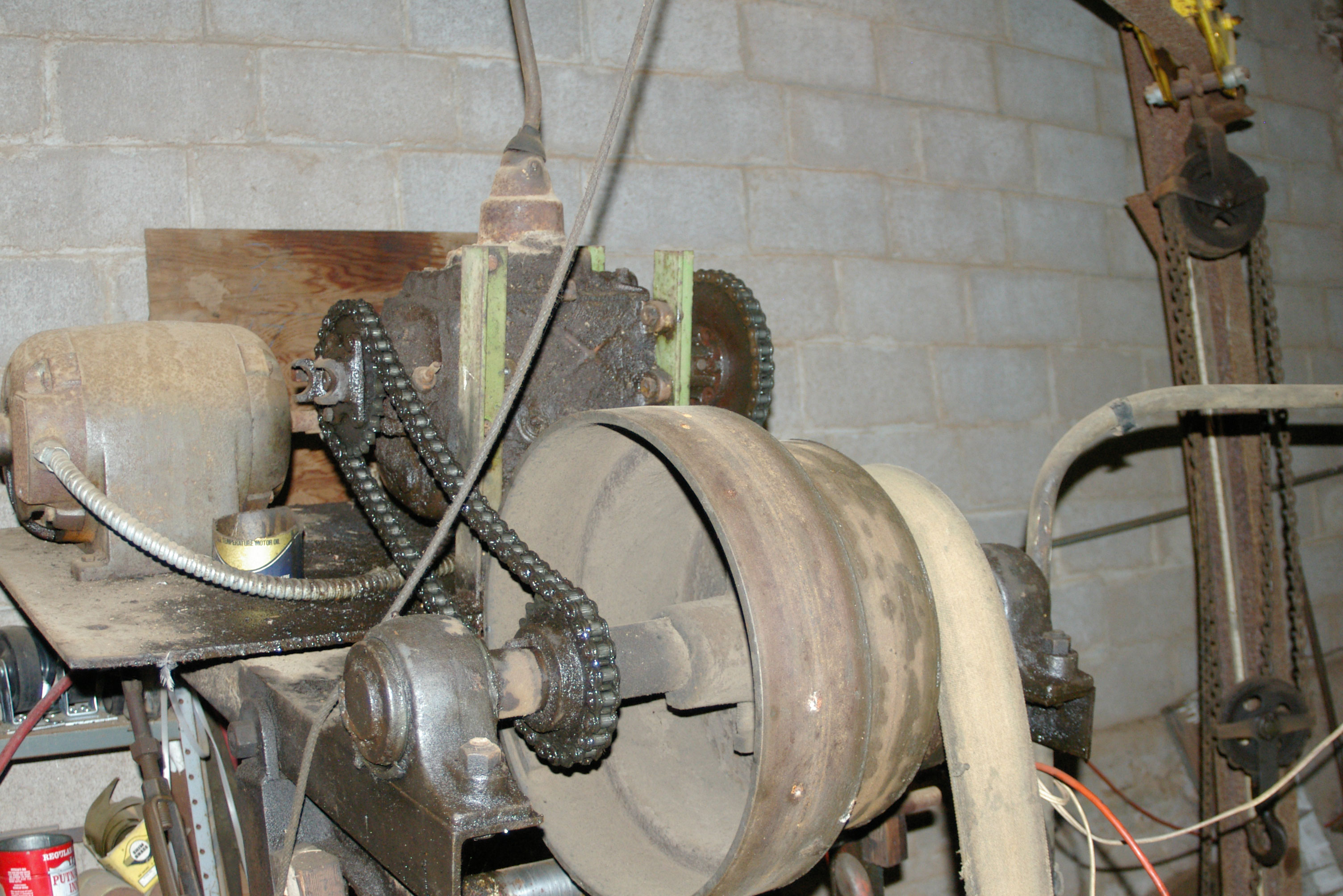
This an an oldy but a goody. The engine lathe is made by London Machine Tools of Hamilton, Ontario, Canada. The specifications are generally 48" in the gap, 30" over the bed and 24" over the cross-slide. It has 15 feet of bed and with 2 out for the tail stock will turn 13' between centers. The total length is about 20 feet.
I have no clue as to the exact age, however, it is a 'loose change gear' lathe which probably dates it to pre World War I, as by WWI it was common for lathes to have shifters on them for changing carriage speeds for thread cutting and actually well before World War I. "Quick change" as it was called was widely adopted by most lathe makers around 1905, although they may have still made 'standard' models after that time. London Machine tools was actually started in London, Ontario, and I have seen a photo of one London Machine tool Lathe of a much older design which listed the place of manufacture as "London, Ontario". They were clearly in Hamilton, Ontario by the time my lathe was built, and since the London Machine Tool name seems to have disappeared in 1912, I'm guessing the age of the lathe somewhere in the middle of the 1st decade of the 20th century. It has a single screw for both the carriage drive and thread cutting which is an older feature, and loose change gears, a older feature, but it does have a hollow spindle and a 3 speed shifter on the carriage drive which is a forward looking feature. Because it is a very large lathe, They may not have been as quick to convert to 'quick change' as with the smaller more competitive lathes. IT appears that the lathe had a removable gap, but it was removed long ago and has never been seen by this owner.
However, CMC bought London Machine Tool in 1912; they relocated the LMT plant to Galt (now Cambridge) in 1917 which provides some confirmation of the age. This lathe is part way there as it has a 3 speed shifter for carriage travel for cutting, and also has a 2 speed back gearing system, but the lead screw drive is controlled by a set of gears and you have to swap the gears around to get the travel speeds for thread cutting.
The lathe uses a single lead screw for three functions. Threading is accomplished via a traditional halfnuts on the lead screw. Alternatively there is a gear on a sliding key which drives a gear train. A pull pin the carriage determines whether this powers a power crossfeed or drives the carriage via a gear train which works on the rack on the bottom of the bed.
Because of this you can have one thread type set in the gearing by default and don't have to change it for standard turning as you can get a high, low and direct on cariage travel in the cutting mode and one thread without messing with things. The High, Low and Direct also applies to the power cross feed.
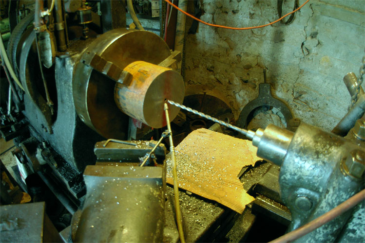
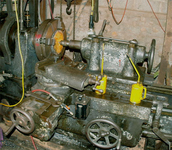
The lathe turns plenty slow enough as set up. A 5 horse motor turns a gear reduction box which is chain driven to a 4 speed transmission out of an old Dodge pickup, and from there to a flat belt which provided 3 speeds. Finally you have 2 back gear speeds. The flat belt is usually what slips so to get more power through the flat belt you try to run the belt speed fairly fast and use the back gears in heavy cutting. As shown the lathe is configured for drilling a large size drill. The tail stock will hold a #5 Morse taper, but bits want to twist so standard practice is to dog the bit and let the end of dog rest on the cross slide. Then you get in low back gear and you can drill right along and never overheat the bit while taking a heavy cut.
We have had this lathe in the family for 25-30 years. Hydraulic cylinders and Pin Bosses have been its usual application. For pin bosses, I usually use a twist drill to get as close to size as possible and then apply a boring bar. I have an assortment of twist drills up to about 2" and beyond that the boring bar comes out. The bag of tricks includes a 15" self centering 3 jaw chuck as well as the 18" four jaw shown. It was as bit of work to mount the 4 jaw as it is one I found at an auction. A really nice steel (not cast iron) chuck, but made for an L2 taper mount. This lathe has a threaded spindle so I had to make an adapter that would thread on the lathe spindle and present a taper and key for the chuck to mount on.
You may wonder what a logger is doing with a machine shop, but if you knew a logger you you know why. Loggers break things. Parts are either not available (profoundly so for our over age and odd ball equipment) or are very expensive. Many time pieces can be made in little more time than it would take to go to town and look for them. We have a smaller lathe as well, an imported 14 x 40 but this beast has done the heavy lifting for a long time. It is not used often but when you need it you need it. Big lathes are slow and this one is really slow. Usually we run it slow enough that no cooling is needed. It has some quirks that you have to work around, such as the fact that it is a gap bed lathe with a removable gap that was long ago removed and forgotten. This creates some issues trying to get the carriage close to the head stock as it sort of slides out into space.
As you can see in some of the photos, we have a gantry crane above it to assist in changing the tooling and to lift things into the lathe. We have several chucks and face places and all are too heavy for a man to lift. Likewise a common duty for a giant lathe is to service giant hydraulic cylinders, and all those pieces are too heavy to man handle.
As an example of a job that was pretty easily accomplished, we broke the webbing out of a front idler on one of our excavators. It was a fabricated idler with 3/8" donut shaped pieces serving as the webbing to hold the ring of the idler to the hub.--- Well the hub broke out. It was either buy a new idler for $1500 and spend a day going after it, or fixing it. We used the day repair it. I bolted the idler to a face place and turned the webbing true, then we made new donut shaped pieces to attach to the hub and plug into the round hole and used the lathe to line everything up and welded things up. The idler is as good as new and we still got the $1500 bucks.
Although 2 jaw and 6 jaw chucks for lathes exist, the most common type of lathe chucks are 3 and 4 jaw models. The 3 jaw chucks are 'quick and dirty' in that they have a scroll plate in them so you can crank all jaws open or closed at the same time, and they will more or less come up true without tedious adjustment. Their limitation is the 'more or less' in that if the work doesn't come up centered as you wish, there is nothing you can do about it. The 4 jaw allows you to adjust each jaw separately with the down side that you have to adjust all of them to get something picked up where you want it.
There is a time and a place for both. It is common to equip lathes with both. Often the 4 jaw will be larger than the 3 jaw. Part of this is a cost issue as 3 jaw chucks cost more than 4 jaw ones and larger chucks cost more than smaller ones. Also 4 jaw chucks are better at gripping odd shaped things and these are often large.
The story here is,however, that chucks have to be changed, and they are heavy. With a small lathe the writers speak of putting a board down on the lathe bed to protect it incase you drop the chuck and just changing them. While the Board is a good idea generally, it isn't much needed on this LMT lathe because it is a gap bed lathe and I don't have a gap filler for it so the gap is always open so there aren't any ways where the chuck would drop if dropped. Chucks for this lathe weight hundreds of pounds so you change them with a chain fall.
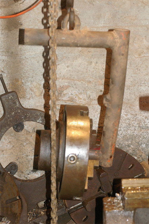
As with most lathes made before 1930, the LMT has a threaded spindle which is about 3 3/4" as I recall. Many large chucks are drilled and tapped for a lifting eye, but this one is not, and so I have a 'U' shaped lifting bracket welded up out of some 2 inch black iron pipe. It is fairly handy as you can insert it into the jaws, spin the chuck off of the spindle and then clamp it down on the lifting arm and swing it away with the chain fall.
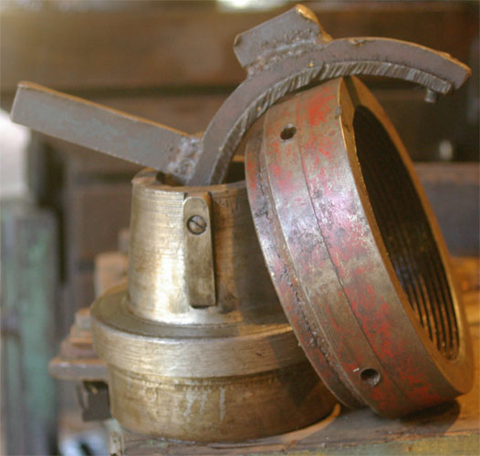
Now I have a very nice steel 18" 4 jaw chuck for this lathe, but when you are dealing with antiques you take what you can scrounge. Normally one would buy a 'flat back' chuck and make a threaded adapter for the back of his chuck. Indeed the project you see on the left will ultimately be a threaded adapter for my ATW lathe. But for this lathe the chuck made by Union Mfg. Co. that was cheap turned out to be an American Long Taper L-2 mount chuck. The Nose of lathes like this have a fairly steep taper several inches long which is keyed, and the chuck is held on with a draw nut. That style peaked in popularity around World War II and there have been few lathes of that style made in the last 40 years. Even more uncommon are large lathes which use the L2 or even larger L3 mount.
Since I was able to scrounge an L2 mount chuck on the cheap, I simply had to make an adapter for it. What you see in the sequence of photos on the right is that adapter. One end is threaded to screw on the spindle and the other end is tapered and keyed to receive the chuck. there is a collar in the middle to retain the draw nut which holds the chuck securely on the taper.
I've moved this project to another page so for more pictures and a story of 'The standard' visit the The standard page.
The Project you see taking shape down the left side is the manufacture of a chuck mount for an 18" Cushman chuck 3 jaw chuck which came with a flat back. The target for the mount is my American Lathe (ATW) featured on another page, but the work for it was done on the London.
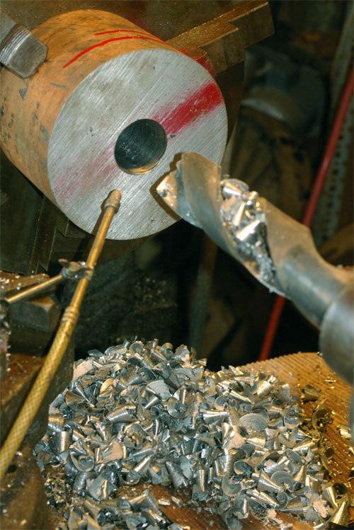
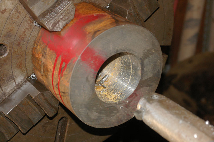
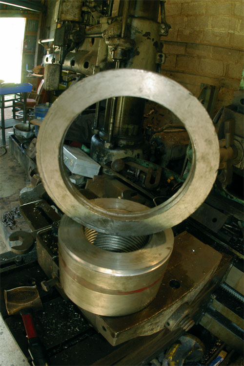
What you see is a piece of shafting 7" in diameter and 5" long, being first pilot drilled, and then progressively drilled larger to the largest drill bit that I have, and then bored to 4".
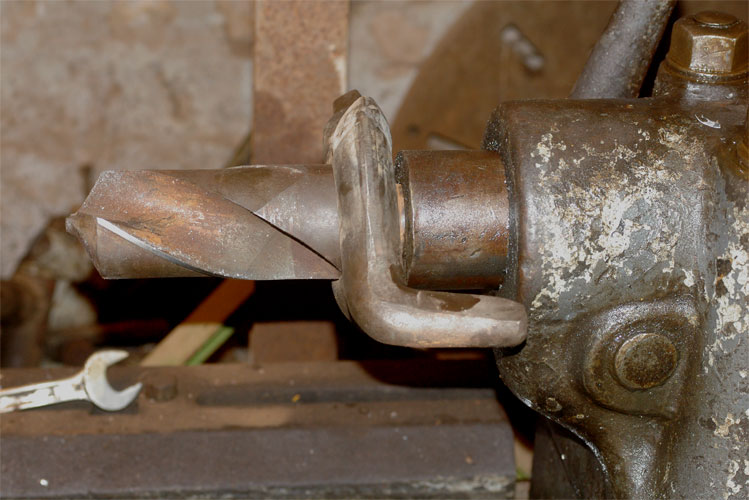
Then you see me start out with a piece of 3/4" flat plate salvaged from a junked out log loader and cut nominally round and then turned to a donut to fit over the hub. Note that I left a step in it, and made it a driving fit with a brass hammer so it would be fairly true. The two pieces will be welded together and then faced off, and the ring turned to the final diameter to fit the chuck. However this final work will be done on the target lathe so regardless of any inaccuracies of my work here, the final cuts will make it true to the target lathe. The largest drill bit that I have is a 2-3/4" bit. It takes a lot of torque to hold it, and sometimes it wants to spin in the tail stock. Standard machinist practice is to put a dog on the bit and rest the end of the dog on the compound. This prevents the bit from spinning. I usually set a steel block on the compound to take up the vertical space between the dog and the compound.
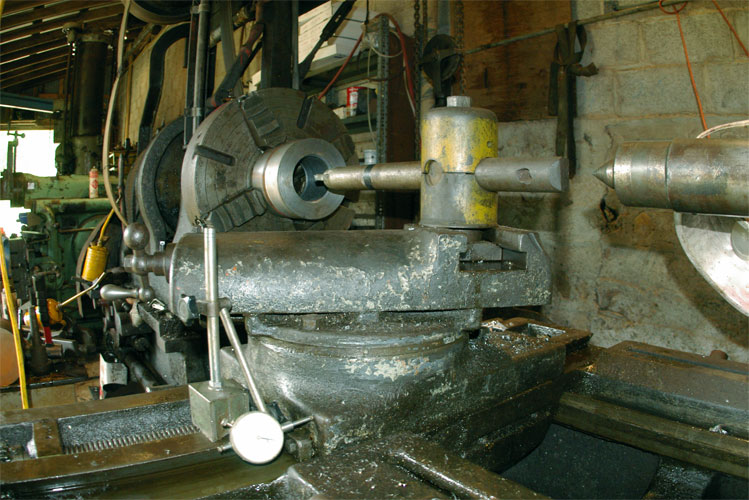
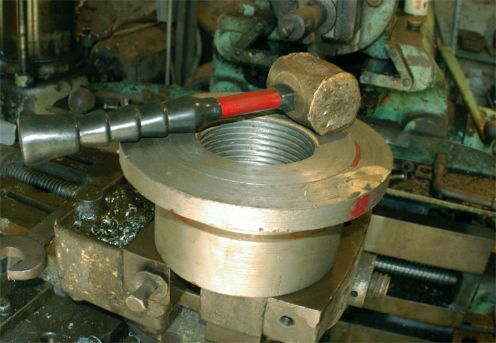
Of special interest here is the setup for threading. It is not conventional. It is customary for threading to set the compound to 29 degrees from straight and then cut your threads by advancing the compound. Since standard threads have a 30 degree angle, you will essentially slide down one side of the thread cutting very little on one side. That is all conventional. What is normal however is that the compound is normally rotated 180 degrees from what you see here with the handle on the back side of the lathe. Presumably because of the extra travel required to reach the large diameters of the gap, the traverse simply won't go over far enough to allow you to bring the compound to bear in the 'by the book' fashion, so you have to 'pull the threads in' by rotating the compound with the handle end toward the front and then use a long boring bar. This is, of course, not an issue if you are cutting outside threads. It would also not be an issue is you were cutting large diameter threads (larger than around 24 inches) as you could turn the compound around and reach just fine. Because the gap filler is gone, the lathe has some issues with working close to the headstock because you can run the carriage out on nothing which is not a good thing.
The lack of a gap closure, and some issues with the gear train in the apron were both reasons that lead me to want to 'upgrade' to a better large lathe. I bought the American on that premise assuming that it was not only better, but newer. I still think it is in better condition, though I haven't run it yet, but it certainly isn't newer, as I have dated the American as being of an 1895 design, likely built between 1898 and 1905, marginally older than the London lathe.