


|
|
|
|
| TL-6 in Second Growth |
|
|
|
|
|
|
|
|
|
|
| Heavy steel rear door |
|
|
| Shop made Wichita brake on haulback |
|
|
| Lower drum for yarding, upper drum for haulback |
|
|
|
|
| The control panel |
|
|
| Logic change valves for downstairs. |
Washington is as famous a name as there is in the history of logging machinery in the Pacific Northwest. They began in 1882 making steam powered donkeys for the mighty logging operations in the Pacific Northwest. Their machinery evolved into some of the largest cable logging machinery ever built.
In the 1960's and '70's they produced both towers and swing machines for cable logging. For example, one of their larger machines was a Model 217D which featured a 110 tube type tower mounted on a self propelled chassis. It featured triple drums, plus a straw drum and 8 guy line drums. The skyline drum held 3000 feet of 1 1/2" cable while the skidding drum featured 2000 feet of 1 3/8" cable. Yarding speeds of up to 2000 feet per minute were possible from a V 1710 Cummins engine (over 500 horsepower).
The focus of this article, however, is on a companion machine called the TL-6 Trakloader. It appeared in both track and rubber mount combinations though the rubber mount seemed more popular. The TL-6 was a combination heel boom log loader and short reach yarder. It was just a double drum machine holding 1,080 feet of 7/8" line on the main drum and 1650 feet of 5/8" line on the haulback drum.
It was standard with either a Cummins 855C or a Detroit 6-71 with a 240 horsepower setting. LIne speeds range from 600 to 1200 FPM depending on how full the drum is. The older machines used a hook roll turntable but the later ones used the giant ball bearing common to excavators today. The TL-6 is 12 feet wide, 16 feet high with the gantry down (and the boom down) and has a working weight of 115,000 lbs with the standard 14,000 lb counterweight. Provision is made for an additional 'water counterweight'. The gantry brings the overall height to 27 feet.. the rated lifting capacity at 85% tipping at a 30' foot radius is 37,000 lbs which is also the rated full drum maximum line pull. Optional guyline drums can provide additional stability for yarding. The typical Guyline winch is mounted on the boom with the line passing through the gantry and going back to a block hanging over the rear of the machine. A loop of cable is in the block with each end secured laterally some distance from the machine. In this fashion the machine can 'change roads' (move along the brough of the hill) to reach additional logs) without resetting the guyline each time. Placing the guyline drum on the boom avoids stressing the gantry lines as the additional stresses made possible by guyline pass directly from the boom to the guyline.

|
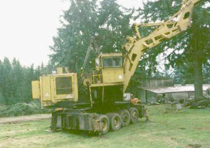
| TL-6 TRAKLOADER |

|
|
Boom off and the gantry down for transport |
|
When used as a loader, this machine equipped with a cable grapple could load the largest of logs without guylines, but the guyline provided the additional stability needed for yarding. As a double drum machine, it cannot do full skyline logging (which needs at least 3 working drums), but it works very well in high lead logging or in a 'shotgun' configuration. In this type of a configuration, the main line is stretched out and is tied off on a 'tail hold' on the back side of the logging operation. This can be to a stump or tail tree if necessary, but where possible will be tied to a large bulldozer. A carriage is hung on this line with the second line connected to the carriage. the chokers are on the carriage.
The carriage goes out on gravity and comes back under power. Obviously, the success of this configuration assumes enough of a hill in the setting that gravity will do its thing. Cable loggers always want to be on top of the mountain. This keeps you out of the creeks, off the hillsides and provides the elevation necessary for the gravity carriage to work.
The engine connects via a Twin Disc multi stage torque converter. The controls are nearly all air. All the winch clutches and brakes are air activated. The outriggers are hydraulic with air activation. Indeed only one hydraulic circuit goes down through the center and with various air servos this single circuit controls all of the outriggers and also handles the steering.
| TL-6 Trakloader Specifications | |
|---|---|
| Height over Cab | 16' 5 1/4" |
| Max Gantry Height | 27' |
| Max Height to top of Machinery House | 14' 1" |
| Tail Swing W/o water Tank | 12' 8" |
| Carrier Length | 21' 1 1/2" |
| Travel width | 11' 11 1/2" |
| Working Weight | 115,100 lbs. |
| Lifting Capacity @ 12' | 120,000 lbs |
| Lifting Capacity @ 25' | 49,400 lbs |
| Bare Drum Linepull | 78,000 lbs |
| Main Drum line | 1060' of 7/8" |
The TL-6 is on 4 axles with a wheel base of only 9 feet. the 2 rear axles are tandem drive axles (Clark model 50-70) with dual 12.00 x 24" rubber. The tandem front axles feature single 12.00 x 24" tires (except in one model that had only 1 front axle with 14.00 X 24" rubber. The rear axles support 75,000 lbs of machine weight which explains why the large tires are used. The 24" tube type truck tires (not to be confused with the 24.5" highway tires now used here and there) will support massive amounts of weight, and are often used in off highway applications when serious weight must be supported.
No speedster, the TL-6 has a maximum speed of 4.4 MPH in low range with a rated gradibility of 24% and maximum speed of 8.8 MPH in high range with a gradibility of 7.5% which practically speaking means that you don't drive it in high range because it won't pull itself as these numbers assume minimal rolling resistance which is hardly ever the case with a machine this heavy.
This sort of machine just assumes that you have a D-8 Cat or two around just to help them move. Alternatively if you need to put some off highway miles on one, they are designed to accept a 'pin on' goose neck on the front. In this configuration, you drop off the drive line, and back a serious off highway tractor under the goose neck which lifts the front axle off the ground and adds the necessary weight to the tractor for traction and away you go, maybe. A push cat or a really good warranty on the truck rear end gears is still a good idea on the hills.
A great old machine, but alas after nearly a century in the business Washington Iron Works is hard to find today. The advent of large hydraulic log loaders blew the cable loader market away, and every increasing environmental restrictions have resulted in the logs that are available often being beyond the reach of this bemoth.
One of the this that always fascinates this writer is how the machine was built. The TL-6 featured here has a date scratched on it of August 29, 1968 'new' which is presumably its delivery date. As you crawl under this machine and look up you notice that the rear driving axles have good sized Clark Planataries inside the tires. The axles are mounted on massive walking beams without springs. The front axles are also mounted on walking beams, but the beams are mounted to a 'flip - flop" which is held in alignment by 4 drag links. The front axles are so close to the rear ones that you can't crawl under the machine between them. You can get under the machine by climbing down inside the front tire and the real axle and sort of squat and duck under i the middle.
Most of the article here is devoted to the use of this machine as a short reach yarder. However, it was of a dual design, and was equally suitable for use as a heel boom log loader. Cable loaders have passed into history with the perfection of the hydraulic loaders several of which are featured elsewhere on this site but before the days of hydraulic loaders which did not begin to appear until the late 1960's, the standard for loading logs was a heel boom loader with a cable grapple. The cable grapple is operated with 2 lines. One is the lifting line and the other is the opening line. This means you can use the same double drums as are used for yarding, and hang a grapple on them. If you lift the grapple by the opening line, the grapple swings open and you can lower it over a log. Then lifting on the other line, the grapple is pulled closed and the log is lifted. If you have done this right, you have hooked the log with the center of balance away from you so the end of the log nearest the machine comes up first. It will hit the bottom of the boom and as you then continue to lift, the log 'heels' and the other end of the log comes up. You then swing over the truck and slack the line a bit and the front of the log goes down first and then you let the back of the log down. When used for loading the boom is lowered quite a bit from what you see in the photos so that the last section is near horizontal. This provides a large flat 'heeling area'. The very front of the boom that stick up is called the grapple riser. This provides space for the grapple which is around 6 feet high to work so that the log can be pulled up so that it is nearly parallel to the boom. This gives you very good control of the log while swinging. If you grab the log over center, the front end will flop up and it won't heel. Conversely, if you get too close to the end, you will either break the end off the log or it will heel with great difficulty. Clearly, if you are lifting a large log in this fashion you need to have a real loader because the weight of the log is prying against you and its center of balance is well beyond the end of the boom. This is why these loaders have massive counterweights. The typical grapple for a machine of this type works fairly well on logs of up to about 4 feet in diameter. For larger logs, the grapples usually have hooks on the outside of the teeth, and a short cable sling with 2 eyes is slipped under the log and hooked on the respective hooks. With heavier logs in particular, the careful operator will grab them fairly close to the center of gravity to minimize the strain on the machinery.
Oh yes, I almost forgot. there is a 3rd wire to the grapple called the tag line. This line will be fed from a small drum and goes out to the grapple from the base of the boom. It is hooked to the side of the grapple, and its purpose is to orient the grapple so it will drop over the log and to prevent the two cables from wrapping up like a telephone cord. Additionally it can be used for 'casting'. This is accomplished by pulling the grapple back toward the machine and the releasing the tag line. As the grapple swings away from the machine you release the grapple and let it drop. With coordination, you can drop it over a log that is well beyond the end of the boom. Machines intended for loader work usually have a small drum dedicated to the tag line which are quite responsive. They often carry the name of a 'Tag Master drum'.
On machines used primarily for yarding the third drum will be for small cable but will be a very large drum as it holds the 'strawline' or 'haywire'. The haywire drum can be used for the tag line if you are loading, but in the yarding mode, the haywire is usually around a 3/8" cable (sometimes smaller, sometimes a little larger), which is used to drag the main lines out in the woods. It needs to be strong enough to pull the main line out, and light enough to be man carried, as that is the way it gets out there. The straw line drum needs to hold twice as much haywire as the main drum has cable. This is because the haywire must be strung out to the back side of the job and then back to the yarder and hooked to the and of the main line. then by taking up the haywire, the main line is pulled to position. The haywire is typically set up to be sectioned in 250 foot sections which can be hooked together by the rigging slinger. The pictures of skyline logging usually show a skyline gracefully hanging from mountain top to mountain top, but somewhere along the line, a brush ape had to pack sections of haywire out there and string them out to get the cable across that canyon. According to tradition there is no canyon that is so rugged that a brush ape can't string a haywire across it, but one wonders, and indeed threre are reports in the logging lore of Oregon that on occasion loggers have hired helicopters to fly the straw line out.

|
| This photo shows a deck of a TL-6 upside down exposing the bottom side. In perspective the deck is 8 feet wide. Prominent in the foreground is the slewing ring with the bevel gear in the center. Next are the air tanks and a hydraulic oil tank with the integrated fuel tank to the rear. The boom base attaches near the front of the slewing ring with the winches and the boom hoist winch anchored above the slewing ring directly behind the boom. The slewing ring is nearly 6 feet in diameter implying that all stresses are focused above the slewing ring. Consequently, although the tail swing is long, the structure behind the slewing ring is consistent with supporting the weight of the the features back there including a massive counterweight but does not need to support the stresses of the work. This deck was in the process of being scrapped and to the credit of the engineers there are no cracks either repaired or otherwise in the deck structure. |
Once under the machine you see that the 'circle' is almost directly above the front of the front differential. Since this is a mechanical drive from upstairs, this is a problem. Washington solved it with an immediate bevel gear and a drive shaft that runs forward to the very front of the machine where there is a 2 speed drop box. From there a second drive shaft runs back to the front of the driving tandems. The controls on the machine are virtually all air. The 'downstairs' functions are no exception. A total of 10 air control lines and 2 hydraulic lines come down through the center of the circle via a rotating valve assembly. These circuits individually raise and lower each of the 4 stabilizers, operate the brakes, and steer the machine.
This is accomplished with logic changes. Computer controls hadn't found their way to logging machinery in 1968, so the logic boxes are air valves. Based on a logic control in the cab, the 2 hydraulic lines are either routed to the steering or to a spool valve farm where the air lines activate the spools for the various outriggers. Of course the matter is even more complicated because the air lines are just servos, as there is a big air tank downstairs, and the control lines are just activators. I don't have it all figured out, but don't underestimate the number of air valves in the lower unit. the brakes are, of course of the spring lok variety so there are 2 air functions to control the brakes, one to release the spring brakes and a second for brake application.
Unlike many machines where you wear the cab like a pair of pants, the cab on this machine is 4 ' 6" wide and made of 3/8" steel plate. The cab would not likely collapse even if another logging machine fell on it or a log was dropped on it. Access is via a door in the back of the cab which swings open on a small porch with a railing around it. From there it is down a ladder and along a catwalk toward the back of the machine. From there you can step to the lower unit and scramble down over an outrigger to finally get to the ground. The large cab is equipped with a heater, large windows, and an incredible number of controls. Central are 4 air treadle valves, and 2 triple function air joy sticks. and a multitude of other air valves. There are a plethora of both hand and foot controls. The 4 treadle valves operate the throttle, the wheel brakes, and brakes for each of the main drums. A air- joystick on the left is a hand throttle when pulled, and swings the machine until you reset a logic switch to put the machine into the 'travel mode' at which time the left joystick steers the machine with the left and right actions (assuming you have air). a hydraulic spool valve is also accessible with the right hand to operate the steering as well. The drum drives are on the right hand joystick with thumb buttons on the respective joysticks to raise and lower the boom. With virtually all of the controls air, there are hundreds of small air lines running around this machine, (and very few wires).
The wiring on this machine was and is very simple. Provision is made for 4 huge batteries right beside the starting motor on the engine. It's not that a Detroit is that hard to start, but here you need enough 'umph' to turn a 34 CFM compressor, a hydraulic pump and rotate some shafting in the machinery area as well as start the engine. That is a lot of stuff to spin up on a cold morning. Beyond that, wiring is almost non-existent. There is an electric start and stop buttons, and an electric activator for the air horn and provision for a light or 2 and that is it. Yarders are also usually the command center for a logging operation and a couple of radios are also usually installed. Indeed, 3 radios would not be uncommon, a CB to coordinate the log trucks, a 'talkie tooter' for communications with the rigging slingers, and a 457 mhz radio for communications with the outside world (via a repeater and a phone patch)

|

|
The shell over the back of the machine is made of 1/2" steel plate. The 6-71 Detroit sits crossways in there. By climbing over the drums you can duck and step over the torque converter and walk around on the back side of the engine. This is necessary to check the engine oil. The generator is cam shaft driven off the back of the camshaft. A massive belt pulley on the front of the crankshaft provides the drive for an even more massive air compressor. The compressor stands as tall as the Engine does, and is of the 2 stage variety as the working pressure for the air controls is 150 PSI. It looks larger than a 15 CFM compressor and is likely a 34 CFM unit. The final 18" of the rear of the machine is an optional water tank. This serves an an additional counterweight, and has connections for a fire hose if worse comes to worse. Also inside the back of the machine room is plenty of space for a 135 lb grease bucket with an air pump on it. Even a bracket to hang the grease hose on, and a dome light yet. The Water tank is donut shaped and there is a back door to the machine (made of 3/4" iron plate. Don't forget your scissors truck if you want to access it, however as the bottom of it is about 10 feet straight up from the ground.
The drums are of a classic design. the torque converter turns a multli-part chain and from there the power train goes through large shafts and open gears. The drums turn freely on the live shafts. Next to the end of the drum is a cast plate which is keyed to the shaft so it turns and will slide on the live shaft. Frictions are bolted to the drum side of the plate, and the drum is engaged by air pressure sliding the frictions against the end of the drum. Rotation is stopped with a band brake. Other than the substitution of air cylinders for long mechanical levers this technology has not changed much since the days of steam donkies.
There are glimmers of newer ideas on the machine however. The boom hoist is a gearmatic auto braking hydraulic winch powered by a hydraulic pump off the front of the engine. There are, of course, air controls on the spool valve for this function. This is a great improvement over the older technology which required you to adjust the boom with a friction drive and then remember to set the mechanical dogs so it would stay there. These worm gear drive hydraulic drives just don't unwind by themselves.
See also Thunderbird Yarder and Logging History for more on cable logging as well as the rigging and carriage pages in this section.
Logging with the TL-6 generally involves a crew of 4 people, though three can almost do it. There will be a machine operator (to run the machine), a rigging slinger (to set the chokers), and a chaser (to unhook them). The fourth person is needed to do something with the logs after they arrive. This sort of a machine usually works along a road rather than at a large well developed landing. As a swing machine, logs are landed to one side of the machine, but usually there is only space for a few logs before the pile becomes unstable. We yarded in tree length and moved the logs away with swinging grapple skidder, but many operations use a loader, and move the logs directly from the hotdeck to the truck if possible. Our approach is to leave some high stumps on the downhill side of the road, and drag the trees down the road for bucking and stack them against the stumps until the truck arrives.
For those who don't know what a 'sail guy' is: A sail guy is unlike a classic guywire is one that only comes tight when needed. On this machine, there is a single guy wire winch mounted up on the boom, it feeds a cable through a block on the top end of the boom which then goes back and is tied to a stump behind the machine. You set the length of the wire so that it comes tight when the machine is swung to the yarding position. When landing the trees you swing to the side and the guy goes slack which is not a problem because the machine has a lifting capacity far greater than that of any log turn that you can yard in. This contrasts radically from a tower type yarder that depends on the guywires to keep it standing up. They for a host of reasons need multiple guywires which are tight all the time. We have boom stops in place so a snap guy isn't needed to keep the boom from flipping over backwards in case of a rigging failure.
In a 'road logging' configuration which we prefer for this type of a machine, the road is along the high ground and you move the machine and the tail hold alternately. Often times you can get a couple machine moves out of a single guywire placement, or even more if you use a walking guywire. Unlike a tower which is a big deal to move, with this machine you just pick up the stabilizers and drive it ahead which only takes minutes as it drives from the seat as you yard from. You actually use some of the same controls to drive it as you use for yarding. It has a logic change control so for example the joystick that is the swing becomes the steering, etc. Oh yes, a 'Walking Guy': Instead of running the guywire back from the boom to a stump, you put a block on the end of the guy wire and run a cable strap between two trees (and through the block). It then works like a dog run and will find its place anywhere between the two ends of the strap.